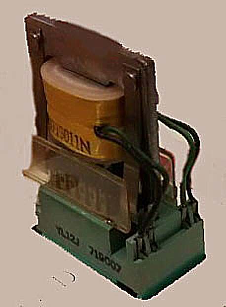
The picture above is of an IBM Permissive Make relay.
It was used in a number of IBM machines including the IBM 1402 card reader punch.
The Permissive Make relays were RED (4 switch contacts) or GREEn (6 switch contacts).
Both of the 1401 computers at the Computer History Museum (CHM) are over 53 years old.
With over 100 of these relays in the 1402, the 1402 has problems that are hard to track down,
Even if a single relay is idntified, it is hard to test a relay to verify if it is good. .
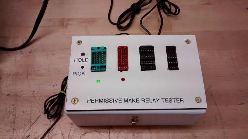
The picture above is on a Permissive make Relay Tester built at the CHM.
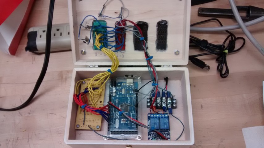
The white box contains an Arduino ATmega2560-16AU processor board, a two relay board and wiring from the PM relay sockets.
The two sockets are wired in parallel with the exception of the top two sets on the red relay.
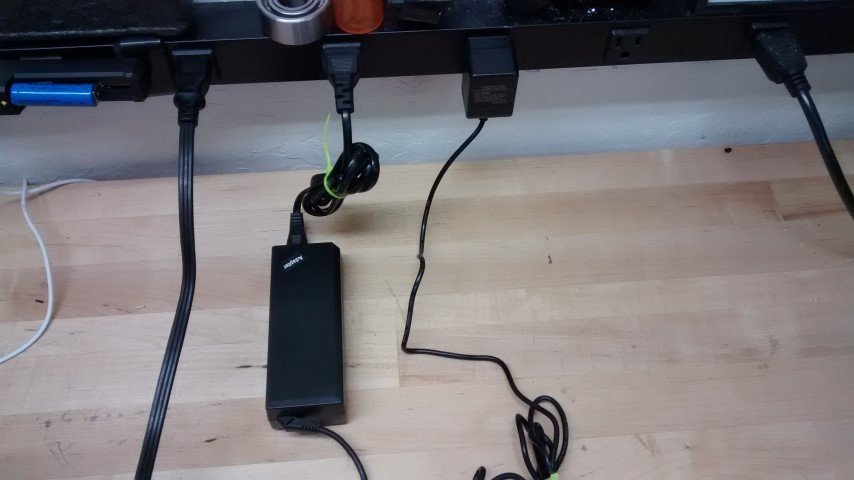
The box requires external 5 VDC to load the relay contacts and 20 VDC to energixe the PM relays.
The two sources of power are shown above.
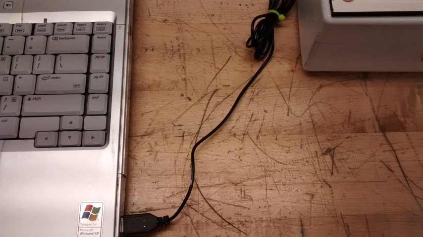
The processor itself is powered by the USB connection to the PC.
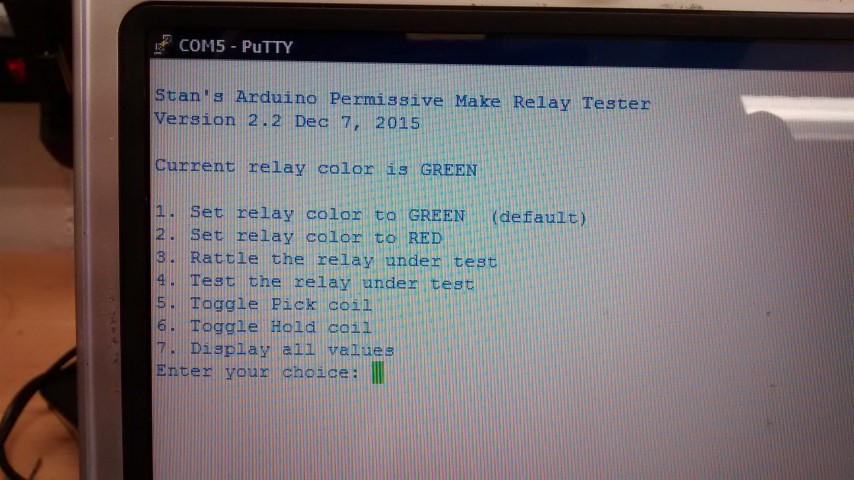
The program running in the Arduino communicates with the PC screen and keyboard via the USB connection.
1. Set relay color to GREEN (default)
Pressing a 1 will set the default for the test to GREEN.
A GREEN LED will light up under the GREEN relay socket.
2. Set relay color to RED
Pressing a 2 will set the default for the test to RED.
A RED LED will light up under the RED relay socket.
Since the GREEN and RED sockets are wired in parallel the only
difference is how many contacts are tested.
12 contacts for the GREEN relays and 8 contacts for the RED relays.
3. Rattle the relay under test
Pressing a 3 will cause the relay under test to cycle 1000 times.
This will knock dirt out from the contacts.
It works even better when contact cleaner is sprayed on the contacts
while the relay is cycling.
4. Test the relay under test
Pressing a 4 will test the relay under test.
The percent values are a quality measurement of the contact.
98.1 is an A+.
Below 90% is a F-.
The PMR will look for the lowest value from all of the contacts and show it on a line by itself.
5. Toggle Pick coil
If the user wants to manually test the relay, the pick coil can be energized by pressing a 5.
The pick LED will light up.
Pressing a 5 again will release the pick coil.
6. Toggle Hold coil
If the user wants to manually test the relay, the hold coil can be energized by pressing a 6.
The hold LED will light up.
Pressing a 6 again will release the hold coil.
5 and 6 are independent of each other and may be used in any order.
7. Display all values
The Display all values function is used when the Test (4) key is pressed.
If pressed by itself, it will display the data from the last test (4).
Enter your choice:
Any number between 1 and 7 may be entered.
Any other character will cause an error message to be displayed.
The PMR reads one character at a time.
You can enter a number of commands and they will be executed in order.
4,3,3,3,4 will test the relay, cycle the relay 1000 times, cycle the relay 1000 times, cycle the relay 1000 times, and test the relay again.
This allows you to determine of the cycling helped the relay
Testing Concept:
Each Normally Open and Normally Closed contact is connected through a 32 ohm resistor to 5 VDC.
All of the common contacts are connected to ground.
When tested, 150 ma flows through the contacts.
The Arduino uses 12 of it's A/D ports to measure the voltage at the contacts.
The health of a contact is measures as a percentage.
The best we have seen so far are 98.1%.
Anything over 90% should be OK.
Test Method
1. Remove the plastic cap from the relay to be tested.
2. Plug in the relay to be tested.
3. Command the box to rattle the relay twice (33)
4, While the relay is rattling, spray contact cleaner on the contacts.
5. When it stops rattling, enter 4 to test the relay (less than 2 seconds)
6, If it is not OK, start at step 3 above.
7. If these steps do not make the relay work, youmight have to replace the contact wires.
Parts: All of the parts used in building this project are available off the shelf and should cost less than $100.
Contact Stan Paddock at CHM for the Arduino source.
Last updated 12/8/2015