Schedule August 2007
return to main 1401 Restoration Page
go to Team Bios
Contents:
Wed August 01 - general
- This report from Ron Williams
Present - Ron Williams, Bob Erickson, Bill Flora, Joe Preston, Frank King, Robert Garner and a knowledgeable visitor Stan Paddock- Frank King visited with Alex and Dag - triggered long e-mail
- Bill Flora - helped everybody
- Joe worked on Sellam's keypunch with Stan
- Bob and Frank King worked on the 513
- Ron Williams worked on slow rise times in the 1401, and was trying to get Full Storage Print to work.
Background: When the 1401 system is equipped with a 1406 Storage Unit, a special mode is available to print the contents of all storage positions. This does not work on our machine.
- (The regular Storage Print Out mode, that prints 100+ characters of memory each time the switch is pressed does work. )
There is a problem with the ALDs -
- - the ALDs of the 1406 interface to the 1401
- - do not match the ALDs of the 1401 interface to the 1406.
The required signal levels just plain don't match.
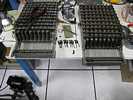
A previous interface problem was solved by designing in another inverter to correct that problem.42.xx.xx area logic doesn't agree with prints - our ALD's are not consistent with the machine. The ALDs should be custom for machine, these ALDs look like bits and pieces collected from several sources. Some seem to have been used for instruction - highlighhting - neat summary logic drawings. Maybe we should get a copy of the ALDs the people in Sindelfingen have. That might be helpful, and might better match this machine???
Wed August 8 - general
- Present were: Ron Williams, Bob Erickson, Bill Flora, Joe Preston, Frank King, Judith Haemmerle, Ed Thelen. Ron Crane came in about 3:00 in response to a "help us" call :-))
- Joe Preston worked on Sellam's keypunch again. For the first few minutes after turning power ON, a circuit driving a clutch does not work properly. It seems a real puzzler.
- More scenes - Ah yes, and there were surprises. During the unloading of the overstuffed Werner basement, things appeared from behind stacks of boxes and other things. Some of these were unplanned from the original reconnaissance trip as there was no way to see them.
Frank used his best judgement about bringing unplanned things and documents - such as the top of this 026 keypunch cover that appeared from under the stairway from behind stacks of boxes. This cover matched the base of an 026 that we had seen in another part of the basement. Click on Warner basement for a much more complete picture list. 
- Joe Preston asked Allison about the new warehouse ... . Allison replied that the facilities people were still working in there. Maybe later this month there will be an announcement for volunteers to help do some serious moving. I think she said that this is a very modern facility with moving storage bays - but the conversation was complicated and my ears were plugged up from a previous cold.
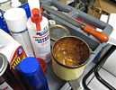
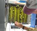
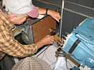
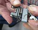
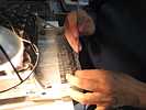
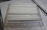
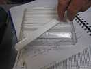
And now our "What is this used for?" contest. - Unfortunately we don't know the answer. The inside wood looks like a tongue depressor - say "AHHHH" 
- John Van Gardner responds Aug 10, 2007
The unknown tool in the attached picture [above right] is a head cleaning tool used on the IBM 2314 and 3330 disk files. You removed the plastic sleeve and soaked one end with 91% isopropyl alcohol P/N 2200200 and inserted it between two heads where the disk platter would normally go.These were the last disk files we had to clean heads on as the follow up machines all had sealed HDAs (Head Disk Assembly).
Van Gardner
Techie Talk: How did Ron measure the current with out a special DC current meter nor breaking the circuit?- If curious, read on :-))
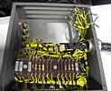
There is a wire from the terminal block to one of the insulated stand-offs visible on the power supply with the arrow. There is a 24 millivolt drop across that wire. If one had the wire resistance, one could calculate the current - but how to measure the resistance with out special equipment and messing with the wiring? Ron Crame asked for a 12 ohm resistor, Ron Williams found our bunch of 6 ohm power resistors from Grant Saviers. Ron Crane said one of those would be just fine. Ron C. placed the resistor so that an extra 2 amps flowed through the wire in question, and again measured the voltage drop across that wire. Hmmmm 0.026 millivolts - the extra 2 amps was causing an extra 2 millivolt drop - the wire has a resistance of almost exactly one milliohm (I have been using rounded numbers for simplicity). 24 millivolts across a 0.00106 ohm resistance gives 22.5 amps. Yeah - anybody could have thought of it - but didn't. Rod Crane did :-))- Interesting thought - the temporary (maybe 8 seconds) extra 2 amp load did not trip the trippy circuit breaker.
- Now, what if anything should we do about the greater than rated -12 volt load and trippy circuit breaker? Ron Crane suggests looking for unusual loads in our fully loaded machine, with optional hardware multiply/divide, overlap, expanded memory, mag tape controller, buffered printer, indexing, British sterling conversion, ...
Saturday August 11 - 2nd Saturday -
- Present were: Ron Williams, Bob Erickson, Judith Haemmerle, Ed Thelen.
- Harlan Snyder came for a visit later - Harlan has had, and is having, a really tough year healthwise :-((
- Matthias Goerner came by with his mother. Matthias is working at a startup, which wants him to work 7 days a week - and he was knocked off his bicycle and hurt for a week, and his girl friend would like to see him a few minutes as week, and Berkeley is calling, and ... We did a BIG PRINT for his mother and she gleefully delighted :-))
- Some photos below by Judith.
- The IBM 513 group, Bob Erickson, Judith Haemmerle, had a tough day.
The MarkSense sized die does not fit into the our 513 frame. Looks as though Bob will have to repair the originally damaged columns 70-80 in the original unit rather than simply do a swap.
Bob discovered that the replacement (mark sense option) punch assembly and die unit were incompatible with the somewhat mangled original (non-mark sense) punch assembly and die unit. 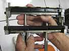

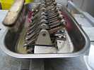
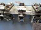
- Then Bob Erickson was having trouble timing one Circuit Breaker, (the timing kind, not the overcurrent kind). He soon realized that the difficulty was that it was not snapping closed as it should, but the arm rather slowly lowered the moving contact into contact with the fixed contact.
What could be this?? Old hard grease?? A cleaning is in order. Here is Judith using the naptha, out doors!! Now everything is snappy again :-)) 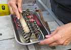
Bob and the 513 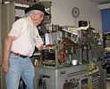
What happened to this brush?? 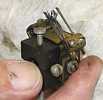
Will this go back in?? 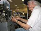
Cogitation 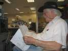
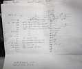
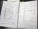
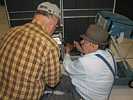
- But Ron had a tough day also - we got the two pages of ALDs from Sindelfingen onto 11x17 paper (Al Kossow was in today and did the CHM network printing from the 1401 web site. The "new" ALDs were quite different (and more closely matched our machine) than the ALDs that came with our machine :-|
- Ed "helped" Ron Williams with a slow pulse problem. Ed soon realized that even though Ron can be a "Terrible Tease" ;-)) Ron can also be a "Tactful Tutor" - gently guiding the student into "discovering" interesting facts for (him)self - and politely keeping him from seriously harming anything :-|
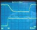
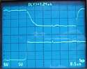
- So, what to do to try to speed the pull down of the voltage to reduce real and potential system problems? A possible solution would be to add a parallel driver to the single overloaded driver. (This is considered very poor engineering practice as the failure of one of the drivers would leave a potentially intermittent situation that can be very difficult to diagnose.)
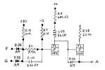
- Nature is conspiring to force us to do "the right thing" :-)) OK - we can do that. The slow load signal is on pin A of the card, the card schematic indicates that the pulldown transistor is T-4. We replace that 083 transistor (minimum large signal beta of 10) with a hot (beta of 80 minimum) type 1308 transistor. We plug the "hot" card in - NO DIFFERENCE - what is going on??
- Ron solders another hot transistor into the T-2 position - yielding the somewhat better signal shown above.
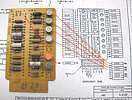
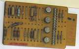
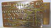
Here is a top and bottom view of an SMS DGQ card to "reverse engineer" to get a correct schematic of the card. 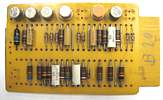
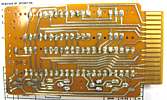
SMS cards - from John van Gardner, August 13 & 14th, 2007
Here is a replacement drawing for you to place over the out-of-date drawing Here is some tourist information for you. I watched IBM make some of the early SMS cards at the Endicott plant when they were first automating the process. I brought home a couple of blank cards and used them to make the attached scan to show how they were made six at a time.
Wed August 15 - general
- Present were: Ron Williams, Bob Erickson, Frank King, Bill Flora, Glenn Lea, Joe Preston, Judith Haemmerle, Robert Garner, Ed Thelen. :-)) We had no visitors :-|
Bill Flora and Glenn Lea started replacing the refurbished parts back onto another 729 tape drive. Joe Preston is in the center, working on the 026 keypunch. 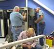
Judith disconnecting the wiring harness for the 513 punch unit magnets 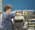
And here is that wiring harness - 
- Ed and Ron took a movie of a narrow pulse that disappears over a period of three seconds after the machine starts in "RUN" mode - very curious -
- Movie clip is being edited.
- Frank King and Robert Garner made a final list of material that Frank help obtain from Werner in Portland to be accessable by the 1401 team for restoration or other usage. The list, in five parts, has been submitted to Alex.
Wed August 22 - general
- Present were: Present were: Ron Williams, Bob Erickson, Frank King, Bill Flora, Glenn Lea, Joe Preston, Judith Haemmerle, Stan Paddock, Ed Thelen. :-)) We had no visitors :-| - again - are we off limits to visitors??
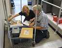
- Basically it was Christmas. Much of the requested Werner material had been released to the 1401 crew. So Frank King and Ed Thelen went looking for our toys ;-)) We found the released material on carts and dollies outside of Allison's cage - all set to roll :-)) (I should clarify - that cage is to secure an area, not keep Allison in !! ) With the permission of William Harnack (Associate Registrar) we started 'em rolling for the 1401 room.
- Frank requested this little experiment - this 024 mechanism from the Werner collection is incomplete - but useful for parts. Frank hopes that pictures can provide a working inventory of what is present and what is missing - for instance, the entire card feed assembly is missing, but there are many useful parts present :-)) The first picture shows the kind and color of the box for easier finding.


- While all the above excitement was going on, Glenn Lea and various others patiently re-assembled one of the 729 tape drives.
Bob Erickson and Judith Haemmerle worked on the 513 reproducing punch.
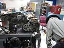
This is a 729 tape drive with many of the electromechanical parts removed for refurbishing at Grant Saviers' work shop. 
And this is a partially re-assembled 729 tape drive. 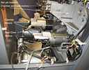
- The 1402 card reader has been giving Read Check errors - even though reading correctly into memory. Bill Flora and Ron Williams are checking the emitter rollers that make contact with the read brushed when there is a hole in the card being read. There are two read stations - with a comparison between them - and error if they don't read the same or illegal punch configuration. One of the rollers shown is a "spare" from another machine.
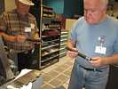

- During lunch Judith gave us a trip report about the Volunteer Appreciation Dinner last Friday. She said that Len Shustek sounded very enthusiastic about having working machines for demonstration.
Then she talked about the interest of the Volunteer Coordinating Committee and the Senior Docents in demonstrating the 1401. Frank and others talked of using the unit record equipment to show how the data flow for a payroll or billing operation is done - and how that data flow was converted to run in the 1401 with out running the cards through so many machines.
There was some question of how the PDP-1 is demonstrated. Specially trained docents or PDP-1 staff or both?
Judith stressed the importance of volunteer hours in getting grants of money from various entities for various projects.
- Jim Somers dropped by and distributed
- - volunteer buttons with that person's cumulative hours,
- - and CHM T-shirts with an image of the Babbage machine on the back.
I forgot to ask how the delivery of the Babbage machine to CHM was coming.
Sat August 25 - 4th Sat
- Present were: Present were: Ron Williams, Bob Erickson, Allen Palmer, Judith Haemmerle, Ed Thelen. Mike Cheponis came in about 3:00 - Mike, Allen and Ed stayed to about 7:00 :-))
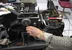
Judith Haemmerle got into what the IBM folks call "brain surgery" - trying to hook tiny springs to tiny whatsamagiggers - something about "interposers" in there. Dig the hemostat holding the whatever - 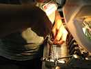
Another view with magnet coils. 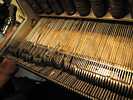
Electromagnets on the other side pull these wires which pull on the springs and stuff that Judith is working on 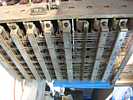
And the point of the whole exercise is to get punch dies selectively forced down through these 80 rectangular holes and up again in a few tenths of a second - to make those nice neat rectangular holes in the cards. No "hanging chad" here!! ;-)) 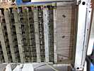
Bob Erickson is shining his light on the 6 cams he is trying to get re-timed. One and a half teeth from correct timing - How the thing can be a half tooth off?? 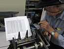
Six breaker to get right - remember adjusting automotive spark timing - one make and one break, then they went electronic :-)) 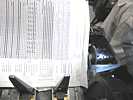
Bet you never suspected it was so complicated to punch a card !! 
- Allen Palmer started connecting the clutch slip ring wiring on a 729 tape drive being re-assembled.
A convenient way connect wire ends is to use these little Crimp-On Butt Connectors. The game is to insert the wire ends into the hole, and crimp the unit firmly, clamping the wires together in a solderless splice. Allen has this unit in a vise to file off the rough part. 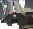
Here is a slip ring brush assembly. The copper circles are the slip rings to conduct current into the magnetic part of this clutch. The green capacitor is new, all these capacitors have been replaced. The yellow ended wire will be connected to the red wire already connected to the assembly. 
Allen is holding the red wire with a bare end going through the Crimp-On connector 
Another view 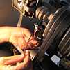
Now both the red and yellow wires have their bare ends in the connector 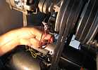
The rusty crimping tool squeezing the connector 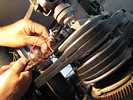
Sometimes the connections fail the Pull Test 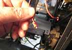
And you get to do it all over again :-((
The splices covered with black tape to reduce accidental contact 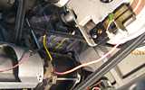
And secured with a tie wrap to prevent contact with a moving abrading belt. 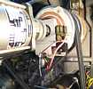
- Allen wanted to show me the joys of using taper pins in 729 tape drives - each reel hub is connected to the clutch shaft with a taper pin. If the taper pin fails, through mis-use, the hub and reel will dis-connect and bad things will happen.
When Allen went to IBM Customer Engineer school for 729 tape drives, a whole morning was spent on the proper way to use taper pins on the clutch shaft.
Executive Summary ;-))
- the hole through the hub sleeve and the shaft is a continuous, smooth sided tapered hole
- - made smooth sided and continous with a tapered tap.
- when driven into place, the narrow end of the pin should not stick out of the hole,
- but be slightly recessed to give a convenient alignment for the drift to drive it out
- - in general, you will have to shorten the small end on the pin to achieve this.
- The large end should protrude from the hole somewhat - this permits a person to feel the placement of the pin because sometimes visual access is limited.
- If you do not take care to achieve the above, the person having to remove the pin can have the following troubles.
- a) he/she will be unable to determine which the small end, and may drive the pin in harder.
- b) if he/she is lucky, he/she will impact the sticking out small end -
- but mash/swell the pin so that mashed end will refuse to go into the hole,
- - causing a lot of trouble.
- c) if the hole is not smoothly tapered, say the hole in the shaft is reversed, the pin will be stopped too soon, and only one side the pin will be securing the hub to the shaft - and it can come out or shear off too easily or will be very difficult to replace.
Typically taper pins are made too long so they can be used in undersized and also worn tapered holes 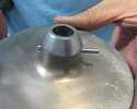
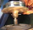
This is the desired small end, slightly recessed for easier alignment of punch for removal, AND support for the sides of the taper pin to prevent mushrooming during removal impacts !! 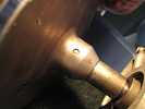
Here is the large end - accessible for further insertion impacts if necessary. 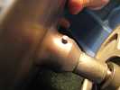
An example - from our system - of the result of improper taper pin usage. the small end was sticking out, and despite great care, mushroomed or expanded or riveted or otherwise deformed and could not be driven out in the normal manner. Sad !! And a great waste of time. 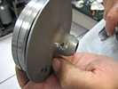
Useful tools - and a vise, hack saw, grind wheel or sanding disk, and care 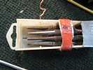
Marking the small end of the pin with a hack saw. Basically, cut a little down from here. 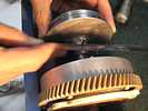
Mark the big end of the hole on the hub - the difference between the big and little are almost invisible 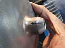
And mark the big end of the shaft hole to assure you don't get it backward and that class of troubles. 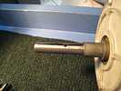
Sawing the taper pin just a little short of the hack saw mark made in a previous stage 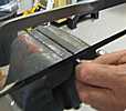
And grinding or sanding to remove burrs left by sawing. Also, you could grind the pin shorter instead of cutting. 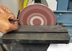
Testing shortened taper pin before final assembly 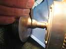
Getting all lined up for final assembly. 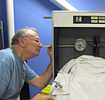
And a solid tap - 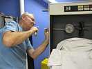
Properly done :-)) 
- Mike Cheponis likes to stir the pot (disturb the statue quo) a bit. ;-)) Mike showed Allen and Ed the specifications of the IBM 729 tape drive family. (We have Models II, IV and V). He questioned how our 729 Model IV drive moved tape at 112.5 inches/ second when the rest of our drives (and industry) moved tape at 75 inches per second. Allen, Ed, and Mike wondered about larger capstan or faster capstan motors. We measured capstans for the Model II, IV, and V in the 1401, they were all about .759 inches in diameter. Hmmm - that must mean our Model IV capstan motor spins faster - No, the name plate rating of the synchronous motors were all identical.
- Was that a Model IV in Visible Storage? It was, and had a capstan diameter of 1.22 inches - just right for moving tape if the motor is at 60 Hz.
- We concluded that Arnold Schweinsberg retrofitted "his/our" Model IV to move tape at 75 inches/second instead of the specified 112.5 inches/second !!! Maybe both he and IBM had trouble at 112.5 inches/second?
Then we discussed those big reel motors - how much power rating did the engineers allow to drive those reels start and stop? 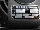
How is this for confusion? 1.35 amps at 220 volts 3 phase is a whale of a lot more than 0.185 kW at a power factor of 1.0. I figure about 890 watts. Considering losses and usual full load power factor, about 1 horse power. - about 746 watts per horsepower. The name plate shows 1/4 that - Nobody builds a motor with such a poor power factor. What is going on???
e-mail "729 Capstan Motors" from John van Gardner August 27, 2007
Attached is a .pdf file of a page from the parts catalog. I have made some notes in red to help understand the IBMeese used in parts catalogs. The right hand column has a code that tells what models use the part listed. The legend for that code is back on list 1 at the beginning of the parts list.
Notice that there is only one part number for the capstan. All models use this part. The tape speed is controlled by the motor therefor there are two different part numbers for the motor. The parts catalog says that PN 526270 is an 1800 RPM motor and this will move the tape at 112.5 IPS. It's easy to calculate the speed of PN 352505 at 1200 RPM which will move the tape at 75 IPS.
I doubt that Arnold put a slower motor in a Mod. IV. This would be a disaster. The TAU unit would sense the signal Select & Ready M4 on pin 20 of the I/O cable and select a write clock oscillator expecting the tape to be moving at 112.5 IPS. The slower motor would only be moving the tape at 75 IPS and the the characters would be written too close together to ever be able to read them on another drive. We called this "Bit packing" and sometimes got if in the front of a record if the prolay wasn't adjusted correctly to get the tape up to speed before writing started.
I hope a record was kept of which motors came from which tape unit. In either case it might be a good idea to scope pin 20 and 31 coming from the tape units and make sure the proper model number is being fed back to the TAU.
Van Gardner
Wed August 29 - general
- Present were: Present were: Ron Williams, Bob Erickson, Bill Flora, Frank King, Joe Preston, Don Lucas, Stan Pollack, Robert Garner, Ed Thelen.
- Judith Haemmerle dropped by to say that she will be attending a class Wednesdays at San Francisco State and will visit us only on Saturdays this fall. :-((
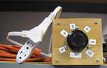
Stan Pollack brought back Bob Erickson's VARIAC all dressed up and safe in this box with cords. - He also reproduced and "stitched" 026 keypunch schematics for working copies.
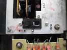
- Ron Williams found a broken solder connection in the "hot wired" from last Saturday (above). Even though the logic seemed wrong, he re-soldered the diode - but the circuit still does not work correctly. Ron says that he will likely come in by himself some time and restore the machine to its original state - including placing the correct switch through the hole in the maintenance panel (above). We suspect that Arnold's circuit never did work as intended.
- We reformed the electrolytic capacitor that was blowing fuses on the Werner 026 keypunch - then Stan Pollock brought out his relay board that will (when connected to the Werner key punch) enable Ron Mack's "ROPE" program to punch object decks using two printer ports of a PC that Stan is donating to the cause.
The Werner 026 keypunch had been "RFQ"ed to interface to a Burroughs computer. The plan is to use the same yellow wires (different plugs, we can't find that unique style on the 026) as the IFM special. 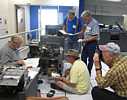
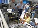

It would be nice to get that unused, unloved second Liebert air conditioning machine out of the 1401 room - it has been in the way for three years. 
- Bill Flora replaced an emitter roller and straightened out a read brush, and the 1402 Reader worked better - Ron said it read one pass of the Ripple Test.
- Bill Flora found Allen Palmer's sign on the 729 saying do not work on it - Bill wondered what to do - and went home.
- Later, Ed Thelen tried to run the BIG PRINT program.
Then tried the ripple test
- - first try, did not read the 1st card (clear memory) correctly - it read the the first column as a blank -
- - second try, hung on second card, a loader card
- - third try, read in all the cards but quit while running the program, a blank opcode is illegal.
I wanted to run the Ripple Read test again (about 1,000 cards, but Ron was worried about wearing out the deck. - We have no back up or working copy, this is the master copy :-((
- - first try, failed to start
- - second try, failed once - on a very early card
- - third try, passed
We tried to reproduce the Ripple Read test deck using the 1402 reader punch but the copy program halted after we punched about one inch of cards -
- It was about 4:00 - a poor day. We decided to go home.
- About then Bob Erickson said that he did something and basically lost a day's work :-((
- We left Stan, Frank and Joe with the 026 keypunch enhancement :-))
Go to September 2007
go to Team Bios

