Schedule August 2006

return to main 1401 Restoration Page
go to Team Bios

Contents:
Wednesday August 02 - general, Thursday August 03 - Tape Team, Thursday August 05 - Special Session,
Wednesday August 9 - general, Thursday August 10 - Tape Team, Sunday August 13 - CHM Volunteer Appreciation, & work,
Wednesday August 16 - general, Thursday August 17 - Tape Team.
Wednesday August 23 - general,

Greeting new Head ["Guest" as of Sept.30] Curator,


Probably no 50 Hz power for the rest of the month, see report for August 23 Latest on 50Hz power
Wednesday August 30 - general, - 50 Hz Power is back


Wednesday August 02 - general,

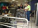
  • Present were: Ron Williams, Allen Palmer, Bob Erickson, Frank King, Chuck Kantmann, Don Cull, Bill Flora, Robert Garner. This report is from comments by Ron Williams.

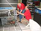
  • Ron Williams, Bill Flora, Don Cull discovered on 1402 punch, position 2 is always an error (open wire connection? - signal might not be getting into the 1401.

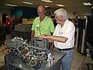
  • Frank King & Chuck Kantmann worked on the 083 sorter

  • Allen Palmer on the tapes (and drums ;-)).

  • Ron Williams suggests that since all instructions are working, it is time for more folks to get practical hands-on console and operating experience - like on the 1402 card reader, which row on the card is "down", How do you insert and run a three instruction loop from the console switches, ...


Thursday August 03 - Tape Team
From Bob Feretich

I worked on the TAU in the morning. Ron Williams joined me in the afternoon so we worked on the card reader ripple read diagnostic (1040A).

TAU Status:
I replaced two cards. One was preventing the read back part of the tape write operation from transitioning from "Read Cond" to "RDD" (read disconnect delay). The other stuck the LRCR bit C to a 1.

Now many write tape operations complete without errors. Errors occur intermittently. Intermittent errors include:
  • A-B Reg compare errors - bits get dropped
  • A Reg VRC errors - bit A sometimes decides to turn itself on
  • R/W Reg VRC error - looks like a false error
  • Mystery error - the error indicator is on, but no sub-error indicator is on
On short records (~5 chars), intermittent errors occur about every hundred records. On longer records, they occur every couple records.

I tried a few tape read operations. The read operation seems to leave the GO interface signal active.  

The cards I replaced (DGT and DHF? (dual trigger)) are in the "bad cards" box. They are my only spares. I would appreciate it if someone can repair them before next Thursday.


Ripple Read Diag Status:
We observed several issues:
  • The data cards have a mistranslated character. Each card contains the character sequence
    " &$%1". The & should be punched as a 12 zone. Instead it is punched as a 0-7-8. I am composing a separate e-mail to Van regarding this. We worked around the problem by setting a break-point (address stop) at the start of the diag and altering the reference field in the diag to match the data cards. See the log for details.
  • We could have permanently patched the deck if we had a working keypunch in the room! Can we get another 026 or 029 from storage? We need one that punches and prints.
  • Sense switch D must be turned on. The diag has many copies of ripple read data. If the switch is off, the second copy of the data is read as a bootstrap image of the next program. All diagnostics decks are designed to chain together.
  • We see intermittent read errors. Errors occur about every 12th card. Usually only one error occurs per card.  Different columns have errors. Column 1 and 3 have more errors than others. Usually a 12 or 11 zone is dropped. Less often a 9 digit gets dropped. Sometimes a 6 gets turned into a 5. We stuffed the diagnostic printout into the CPU log book.   

Regards,
Bob Feretich


Saturday August 5 - Special Session

from Jeff Stutzman
Greetings,

Ron Crane, and myself stopped by the CHM lab late Saturday. Ron fixed two boards Bob found Thursday which one had a bad diode and the other a partially broken lead on a transistor. (less then an hour visit.) The rest of the time we spent going over a TEK 2465 Scope that I bought DOA at an auction a few weeks back.

Ron must of spent more then a few hours fixing it for me as he gave me a bag full of fried parts. The "part hunt" alone must of taken up a good afternoon. I'm amazed that it was brought back from the dead after he found a blown out fan causing major board components to fry. I can't thank him enough... ;-)
jeff-

P.S: The Lab and bench looks nice, I noticed someone cleaned the place up a bit.
I am definitely not the guilty party !!, Just ask my wife !! -- Ed Thelen


Wednesday August 9 - general


Thursday August 10 - Tape Team
from Bob Feretich


TAU Debug: (Jeff S, and I)
The 1 MHz oscillator (used for 800 bpi clock generation) died. We pulled out the card and put it in the "To Be Repaired" box. We continued debug using 556 bpi as high density.

Bugs are getting harder to troubleshoot. We have several different intermittent bugs occurring. It seems that whichever bug we set up the scope to trace stops occurring for a half hour or so. Only the other bugs keep occurring.

When we cam back from lunch, we noticed a strong smell of burning electronics in the room. The smell was throughout the room and we could not identify the source. We shut off everything and waited for the room to ventilate. When we returned and turned on power again, we identified the source as the top (A1) module in the 50 Hz power distribution unit. We turned off the A1 unit. Initially, the load was within limits for the B1 and C1 units to handle, but when the tape drive motors engaged the B1 unit went into the red. (B1 at 16+ amps and C1 at 13 amps). We opened and inspected the A1 unit. No signs of heat damage were visible, so we returned it to service. The unit is still emitting the smell, but it is performing fine electrically. It needs to be checked out by someone who better understands the unit. Some of its cover screws are taped to its front panel.

Continued TAU debug showed that at least one of the intermittent problems was due to tape signal weakening. There are spots on the tape where the Read Bus 8V p-p shrinks to about 7.3V p-p. This error occurred on the read-back part of the Write operation. (The thresholds for this part of the operation are tighter than for a Read operation.) I don't know at what levels the clipping thresholds should be set at, but I would have expected the TAU to tolerate a 10% weakening without complaint. I need to research the appropriate levels. I remember seeing them somewhere. If anyone knows the levels or adjustment process, please reply.

We also identified a bad output pin drive level occurring in the bit "1" clipping amplifier. We pulled the card for repair. We also believe we have a similar problem in bit "A", but we are out of spare amplifier cards.

Ron C.: Thanks for stopping in to repair last weeks cards. Unfortunately, it looks like we will have a continuing need for fast turnaround repairs. BTW: Where did you get the 1N60 diode, I didn't see any drawers labeled with that number in our parts cabinet.

Tape Analyzer Bring-up: (Jeff S., Dave A,. Mark (Dave's friend), and I) We held a meeting regarding firmware development for the analyzer. It was decided that I write the initial version of the firmware. We have scheduled a design review and partial code walk-thru for next Thursday at 4:30. I will write the first version in assembler. Mark and Dave will look at converting the firmware to "C" once the application is working and documented.

Regards,
Bob Feretich

from Grant Saviers
Just from experience and not from IBM documents; I would set the read after write threshold at 60 to 70% of nominal. The read detectors should work in read mode down to about 30% of nominal.

Grant

A thought about margins from Ed Thelen
Margins

"Back in the goode olde daze" - when I was a tad of a lad - ... - and fixed computers for a living ...

There were voltage margins. If there was an intermittent, and I had no other clue, and rattling the cards didn't seem to trigger the problem, the first thing I did was to play the voltage margin game to try to turn the intermittent into a solid failure.

Often tweaking the various voltages caused the intermittent to fail hard, and be much easier to fix.

Even when things were running well, I would tweak the voltages (and room temperature) every few weeks to assure that the machine was not getting sensitive to marginal conditions.

The 1401 has quite a voltage margin system,
my suggestion would be to give it a try when faced with intermittents. ;-))


Sunday August 13 - Volunteer Appreciation & work

Probably 10 from the 1401 Restoration Group went to the CHM Volunteer Appreciation BBQ. I thought it was very well done. There was quite a mob ?275??, seemingly all were well fed. Then a computer trivia game, and John Toole, Dave Dial & Len Shustek informed about CHM finances and future plans.

At the conclusion, hero metals were awarded for the number of hours of service to the museum the past fiscal year. Ron Williams got so many hours that (Many of the 1401 group don't record hours, so Jim Somers examines this web site and estimates our hours.)

(A telephoto of) Dave Dial photographing the assembled mob. Apparently we all fit into that little tiny camera :-|

Before and after the festivities, Ron Williams, Bob Erickson and Ed Thelen got several "spare" 50 Hz Pacific Pwoer power amplifiers from the warehouse to:
a) assure that any demo went well,
b) try to figure what was causing the burning/scortched smell Thursday (above).
Steve Russell of the PDP-1 group also dropped by to look for evidence. (We didn't determine a "smoking gun" so to speak, but we did re-crimp a possibly suspect quick disconnect.

Jeff Stutzman came by to give all known details of the incident. He did not see any neon fuse blown warning lights. Ron Crane examined the smelly power unit, then examined one of the "spare" power units that was tagged for having lit neon warning lamps.
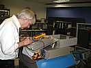
Ron Crane checking the restances of the fuses (0.1 ohm) and emitter resistors (1.0 ohms) and found four open fuses in this "spare" power supply unit.

There are three power supply units per phase, and three phases, totaling 9 units in service. We have 8 spares - four do not have warning tags on them.

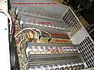
This is the bottom half of one of the Pacific Power amplifier units. The top half is identical, and the fans push cooling air between the heat sinks. You can see the labeled "Heat sinks" to cool the transistors, "Emitter resistors" to spread the current out rather evenly between the transistors, and "Micro fuses" to open if a transistor (paired) conducts too much current.
The Fuse warning neons are not visible in this view, but are visible through the fans when viewed from the front of the rack of power amplifiers.


Wednesday August 16 - general


Thursday August 17 - Tape Team

from Bob Feretich
TAU Status: (Jeff S., Grant S., & me)
The first problem we shot was an intermittent error on the data read-back part of the Write operation. We traced the error to the Read Amplifiers being turned on all the time. Replacing a card fixed the problem, but did not noticeably effect the errors we are observing.

The next bug led us to an error in the schematic documentation of the TAU. This is the first documentation error I have found, so confidence in the documentation is still very high. "Powered copies" of a control signal were created and suffixed "cht1", "ckt2", and "ckt3". The ALD logic diagram showed "ckt3" driving the suspected logic. However, we determined that "ckt3" logically differed from the other signals and was not connected to the suspected logic.

The problem is still unresolved. We are seeing the A-Reg VRC indicator and the Error indicator turn on, but "stop on error" does not stop the clock. We have not been able to find a scope trigger point that allows us to zoom in on the error.

The smell of burning electronics continues permeate the lab. The source still seems to be the top of the 50Hz power converter. The smell gets very strong when power consumption is at maximum. (with tape drive writing) The smell is slight with the tape drive powered off. Since the top module in the 50Hz converter has been replaced, perhaps there is something burning on the board above the top replaceable module. ???
Maybe Ron Crane's infrared heat detector gun will be able to locate the trouble source. In the mean time, we have verified that the fire extinguishers are charged and ready.

Tape Channel Analyzer Status: (Jeff S., Mark, and me.)
We design reviewed the architecture, programming conventions, and skeleton application of the Tape Channel Analyzer firmware. (Kudos to Jeff for patiently listening to the whole review. We did not complete the review to 11 pm.) The review resulted in one major architecture question being raised and several minor bugs being detected. The architectural question involves the correct method to resynchronize the PC and the Tape Adapter should synchronization on the USB interface be lost. (How should we detect the begining of a new message? And, resynchronize when there is a data drop out?)

The skeleton application is designed to implement the subset of Tape Analyzer functionality needed to resolve PC Windows driver latency response issues. (The PC must respond to Tape Analyzer requests across the USB interface in less than 10 milliseconds.) We established the goal to begin latency testing in two weeks. Some PC and PIC programming and much firmware debugging has to occur in the next two weeks for this to happen.

We would appreciate the help of a Windows driver expert on this problem. Right now, I believe that we have the energy and motivation, but not the skills to solve this driver latency problem. Ron Mak is posting our request to the software team mailing list.

Regards,
Bob Feretich

Friday August 18, 2006

A little status report.

I have been a little delinquent in providing update repots on the 729 project. You have not seen me at the CHM for quite awhile as I am still up at Grant's. We have been rebuilding all the individual clutch reels, the drive motors & hi-speed rewind motors.

This pass Wednesday 8/16th was great. I arrived at Grant's , and then Bob followed and later Jeff.

It was decided that we would set up two production lines. One to complete the clutch units and the other to finish to rebuilding of the drive motors.

Clutch reels.

After working for months we had reached the point where the reel units had all been all sand blasted, new powder inserted, new inside felt washers installed and just awaiting the new outside cover plate felt washers. Punching out the felt washers out of strips of felt was / is not as simple as one might think. First it has to be a perfect circle and then within that circle you need to punch out a second perfect circle that is exactly position in the center of the big felt circle. We had two different sized felt washers. Grant designed and machined a two-direction punch block. A strip of felt was inserted, centered over the large cut in the punch block & then the two sides of the block were bolted together. Then using a hand press the large punch was pressed through the felt. Then the block was turned over and a second punch was inserted to take out the center hole and was driven through the felt. Then the blocks were unbolted, separated and the washer removed. This was repeated 30 + times with medium weight felt for set of washers & then 30+ more times again with heavy weight felt. Now all we needed was to punch out and install the back cover washers.

This past Wednesday we needed to repeat the felt washer process but with a new punch because we needed the make washes of a different size. Grant machined the new block & punches. He then started the job of hand punching out the 30+ felt washers we need while I removed the 'C' clip and brass ring plate to get to the old washer, removed it, installed the new washer and reinstalled the brass ring & 'C' clip. We finished them all.

They are now ready to be reinstalled on the clutch shafts into complete clutch assemblies. That should take a few weeks to complete. Then back to CHM.

Drive motors.

The drive motors used an 'open faced, grease packed' bearings (2 per motor). Let us just say that the bearings had served their time. The ten motors (2 per drive) were removed and brought to Grant's where they were stripped down, cleaned and new bearings installed and then put back together again. Bob went to work to finish the remaining motors. It was a very dirty job with oil, grease, dirt, and rubber drive belt slough making for a mess. Bob put the smaller parts in the ultrasound bath and the motor end bell housing went into the kerosene greaser. After he had all the parts looking liking like new, he installed the new sealed bearing and reassembled the motor. Nine of the ten motors have been completed and the last one will be finished next week. Jeff helped out wherever an extra pair of hands was needed. And they were needed.

Hi-speed rewind motors.

There is one per machine and the ModV on the floor has already been rebuilt. That leaves the four others to be rebuilt. I expect that we can do them is one workday.

The next problem to be solved (read designed & individually machined) are the 60 commutator brushes we need ( 2/reel x 3 reels /shaft x 2 shafts / drive x 5 drives). We can if necessary use the ones we have but it would be nice to install the new brushes at the same time we are installing the clutch shafts. Removing & replacing the brush block bracket is very difficult & time consuming. I have spent move than 1/2 a day with Glenn and I working together to reinstall one bracket. Not one of IBM's shining design moments.

And then what?

Like Moses it will be time to come down from the mountain but rather than bearing two stone tablets we will be bearing 8 completely rebuilt clutch shafts, 8 shiny drive motors and 4 little but no less important hi-speed rewind motors plus the items that have already been reinstalled in the Mod V on the floor. Not a lot to show for 10 months of work in the mountains (so I took some vacation but who's counting other than Robert) or so it might seem but a lot a trail and error, testing, machining parts & tools, you name it, to get this stuff rebuilt.

The other ModV has been completely cleaned up, had its power supplied pulled, tested and reinstalled and needs to have the drive motors, hi-speed rewind & both clutch shaft reinstalled which will complete the mechanical rebuilding. This should take abet 2 work sessions. Then we can turn on the power and see if & how well it executes commands. Time for that - unknown. Then it's time to cable it to the CPU.

The other 3 drives will follow the same pattern. Their power supplies have been pulled and have been turned over to our very excellent power supply rebuilder Capt Ed. The drive frames themselves have not been physically cleaned but once they are, we will work on them as above. With help we can work on more than 1 drive at a time. These drives pose the possibility for greater problems since most of their control circuitry are relays- many different types - mechanical timers, heavy power driver transistors.

And by February/March '07?

We should have 4 up and running drives. Why not 5 - if we need parts somebody has to be the donor and why not the 5th drive. I am sure it will gladly give up its life to save the other four - it's called 'for the greater good' the same thing government is always saying when it collects taxes.

This concludes my yearly report and what we have accomplished after two + years of work.

I knew that taking this as a fixed bid contract was wrong. Mother said 'go for T&M'. Always listen to mother.

Allen j Palmer


Wednesday August 23 - General -


Latest on 50Hz power

Wednesday, August 23,
- Turned on 50 Hz power in a high state of alert. Quickly smelled (Robert Garner saw) smoke, and we quickly turned off the power. See report
here.

Thursday, August 24, Much e-mail.

Problem discussion

From Robert Garner
Turns out the Pacific Power's control unit (301-F) on top is indeed fried.

The 1401 will be down for at least a week, perhaps two. :-(

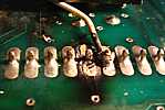
Two pins in a connector between the "Oscillator/Control PCB" and one of the three "Voltage Amplifier (VA) PCB" are cooked, as well as the FR4 around the connector on the Oscillator/Control board. These two pins are connected together on the VA board, called "Black Output" and are the return side of the main 60 VDC generated from the DC supply in the base. Perhaps the small connector was the weakest link (highest resistance) in the path, and took the brunt of an over current, perhaps due to a shorted "overload detector" opamp, where "Black Output" connects to on the VA board.

I'm in touch with Mitch Orr at Pacific Power, 949-251-1800 x 124, who supported this unit back in the mid '80's when it was at IBM Cottle. The good news is that our 301-F control unit is still in production! He said he would try to get us a "deal" on replacement boards.

I'll keep you updated on progress.

Jeff ---> What do we know about that AC, 3-phase power converter you bought at BDI?? Do you have specs for it? Do we know if it works?

- Robert

p.s. Apparently many compliance test labs still use our Pacific Power GR series converter due to it's ability to handle huge inrushes, like our 1401 ferroresonant supplies.


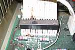
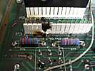
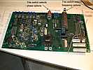
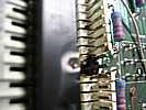
from Robert Garner - Here are two pictures of the fried P3 cable connector.
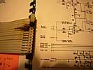
shows it against the destination connections (pins 10 and 11) in the? voltage amplifier schematic, showing the OpAmp that?may have shorted inputs? (but are those are big input resistors I see?)
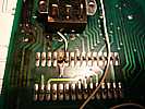
matching fried P3 connector on the Control PCB. (numbered pins 5 and 6 in this case.) Note the rework wire on pin 6. (I wonder what it does as it dives under the big black connector to the 60V DC unit at the base? We didn't probe for a possible short in there...)

Discussions of Jeff's 50 Hz converter.
Another e-mail from Robert Garner
Quote from Pacific Power (attached) is $1,600 and delivery within a week to replace the two boards and connecting cable. This is reasonable, given component counts on these boards.

The fried Controller board is $1100. The Voltage Amplifier (VA) board that we suspect has a failure on it (but don't know for sure, as it looks clean) is $468. The ribbon cable connector is $34.

Before we issue the PO, I'd like to ask Ron if he could examine the boards and get his opinion as to what may have caused the runaway heating. [It turns out Ron Crane is vacationing in Maine.] Perhaps we won't need a new VA board. In any case, we should formulate a decent theory as to what caused the problem before we turn it back on.

We'll also concurrently pursue Jeff's hefty switcher converter, currently docked at Grant's ranch. However, by the time we
test it,
get proper output transformers,
get it delivered,
add possible floor supports,
schedule the electrician to hook it up (assuming we can get 480 VAC into the room),
and then cross our fingers (if it's inrush current challenged),
I think we'll still want to get the Pacific Power restored. (Besides, we may still want to use the Pacific Power again some day, if the big converter works out.)


E-mail from Grant Saviers
There are pros and cons to continuing with Pacific Power vs the Power Star unit


- Ongoing energy costs will be higher for Pacific- about 2x accroding to Ron Crane's estimate.
- Accordingly, heat generated will be 1/2 of what it is now for PowerStar
- Experience leads Bob F to believe the Pacific unit might not power all the tape drives
- Inrush should be better with the PowerStar inverter design (smaller capacitors).
- 460v 3p delta is available across the hall at the main power panel,

but it will cost $1k or so to bring it into the 1401 room.
- Power Star unit needs a 208 to 380 3p Y transformer (20kw about $700 used)
- No pedigree on "powerstar" as a company as yet
- We don't know if Power Star unit works
- a google of "powerstar" yields a lot of hits that need to be searched through.
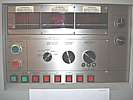
- A picture of the PowerStar front panel is attached.


Nameplate stuff from Jeff's inverter supply and supplied photo

Power Star (cabinet nameplate)
Model A0603-VD1 SN 0233
Warranty Date 6-6-92
Input voltage 480 3p delta
input power 36.6 kw
output 0-140v 100 amps
service phone 800 854 9420 (no answer in 2 tries)

Friday, Aug 25th

Tuesday, Aug 29th - e-mail from Robert Garner
An update on our fried Pacific Power converter board/connector/cable:

Ron Crane, having just returned from an East Coast vacation yesterday, was able to check out the fried Pacific Power control board and associated schematics. His working hypothesis is that the Phase C return current (recently from the 729 tape drive) was being conducted thru a lower-impedance tie-together point in the control boards (that connect the three phase returns together for metering circuits), instead of where it should be, in a hefty control tie strip in the base of the unit. This wayward return path flowed through the two connector pins that fried.

Ron thinks there's a chance we can repair the board and connector ourselves.

He also suspects this may have happened before we owned the unit, as the white rework wires that we noticed on the control board seem to indicate a repair of a similar past incident.

More investigation to continue this evening...

- Robert

Wednesday August 30 - general,

Report by Don Luke
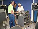
  • Frank King and I [Don Luke] set timing and duration for circuit breakers on the 083 sorter.
  • Al Palmer and Glen Lea were working on a 729 tape.
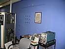
  • Chuck Kantmann was working in Ed Thelen's spacious new office in the lab.
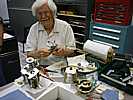
    A picture last month of Tim Coslet in Ed Thelen's spacious new office ;-))

    Inspiration, decor, furniture and sign by Ron Williams

- e-mail from Robert Garner - Wednesday, Aug 30th
Ron Crane has been in the lab (with Jeff) this afternoon and evening, working on the fried power converter. He has repaired the control board (!) connector and the jumper cable/connector, verified DC resistances, and currently has the Pacific Power turned back on, generating good AC levels, no smoke!

He will next be connecting three phase neutrals together in the Pacific Power converter base* and then turning on the 1401 and then 729. I expect it will work just fine.

Looks like we'll be back up tomorrow. He and/or Jeff will send a full report, with pictures.

Now just don't remind Ron about an invoice! ;-)

- Robert

* How did I/we miss that? We had carefully made sure the 3 phase neutrals were tied together in the Elgar power converter, but had not done same with Pacific Power unit. It's strange Pacific Power had (inadvertently?) connected them together via a trace in their control board (a wimpy meter_return signal).

Thursday, Aug 31th - e-mail from Robert Garner

50-Hz power is back up!

Hats off to Ron Crane and Jeff Stutzman (who were in the lab until the wee hours early this morning).

Ron, having just stepped off a plane on Monday, diagnosed the failure and its cause. He has repaired the fried Pacific Power board/cable and re-wired its AC power returns to prevent reoccurrence.

We'll post a longer explanation w/ pictures on the web site. In summary, three issues conspired to create our problem:

  1. We had not verified whether the AC power returns were tied together in the Pacific Power converter, as they should be. (We had done this for our previous Elgar converter. :-)
  2. There's a questionable connection of the AC returns together in the Pacific Power control board for meter display circuits.
  3. The new-kid-on-the-block 729 mainly used the previously lightly-used Phase C power. The dubious connection in the control board (~1/3 ohm) carried the burden of the new, larger unbalanced return current, and its weakest link (the connector pins) burned.* :-(
In our plan is also to look more closely at Jeff's recently purchased, surplused, heavy 36kVA Power Star converter. Because its a switcher, power use, cost, and noise would be lower. Needs to be tested out (inrush handling?), and installation issues explored.

- Robert

* It also turns out that (more significant) frying had occurred to the control board once in its past, before we acquired it. (Based on pre-existing rework wires on the board.)


Go to
September 2006
go to Team Bios