Now to bad news.
What has been done so far makes sense to me and here are two other
techniques we could use for smoothing the shaft:
We can cover the shaft with Dykem marking fluid and then slide a bearing
onto the shaft. High spots will have the fluid removed and then they
can be touched up with a file. Repeat this process until the desired
slip fit is achieved along the entire shaft. This technique is a
standard process for fitting custom made bearings and is also used in
hand scraping items to flatness.
Another option would be to find a centerless grinder grinding job shop
that would be willing to spend a few minutes in tweaking in a grinder to
just touch grind the shaft to remove the high spots. I've watched
centerless grinder operators and know there is quite a bit of "feel" in
doing such an operation and hitting .0001" tolerances.
There are many grades of Loctite, including one specifically for bearing
retention. It will be very difficult to keep any Loctite in the right
place during assembly or to apply it post assembly. The clutches were
difficult to disassemble without any adhesives, so to preserve future
ability to repair them I think we should avoid using Loctite at this point.
The design of the assembly causes all of the bearings, split rings, and
collars to be compressed by the locking nut on the end of the shaft.
Making sure this assembly is tight is important for two reasons:
I was also thinking about the sticking of the woodruff keys and suggest
we apply a very light coating of Never-Seez to them during reassembly
so the next removal is easier. We also need a non damaging key removal
technique for the remaining clutch assemblies. I'll give this more
thought, but am not aware of any special tools made for this, so I may
need to make one.
Grant
http://www.repcoinc.com/carbon_brushes_fld/reference.asp
a very nice tutorial. I couldn't find the basic size we need (.250"
round) on their web site so emailed them an RFQ for 100 pieces
electrographitic of .250 round with shunt wire or .250 square (stock #
REP324W) with shunt wire. In either case we (me?) would need to machine
these to the dimensions of the IBM brush, .25" diameter head with .18"
stem by tbd length. I've never machined brushes but guess it will be
messy like machining graphite for EDM electrodes, something commonly
done in machine shops. A little complication is to do this with the
spring and shunt lead attached to the brush but I don't think that will
be a show stopper with some fixturing.
One never knows what interesting digression will come up next with this
project :-).
Grant
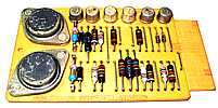
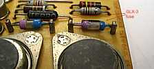
The resistor should have been 20 ohms (although the markings were now charred) and the
resistor now measured 29 ohms. About a 50% increase. It had not yet open circuited.
Kind of disturbing - why would some one come in and rotate the unit 90 degrees?
A photo shoot??
"Victor Chen at the IBM Almaden Research repaired and resoldered
the two wire connections from a magnetic clutch coil to the copper contact ring in the takeup clutch assembly.
(The wires had been accidentally severed when the clutch assembly was pulled apart. New procedure/tool
now prevents this from happening.)"
Grant,
A short update on my progress last Wednesday
- and then some contact information -
Allen J Palmer
All,
I've looked at the drawings and the SMS Manual. Following are comments on
the circuits and component values.
   -N terminator     128.5 (130) ohms to ground and 300 ohms to + 5 V
   +P terminator     100 ohms to - 7V   and 900 (910) ohms to -12 V
   -N signal  high  +1.5V       (driver OFF)
              low   -2.12V      (driver ON )

   +P signal  high  -4.04V      (driver ON )
              low   -6.96V      (driver OFF)
   Signal Level   Voltage   729 driver output   driver state  reference

    -N   high      +.2 V       0 mA               OFF           GND
    -N   low       -.3 V      -6 mA               ON            GND
    +P   high      -5.7 V     +6 mA               ON          - 6 V
    +P   low       -6.2 V      0 mA               OFF         - 6 V
  -N Driver        ____________
                  |            |    1N4148      1K *
    TTL level ----| 75188      |------|<|-----/\/\/\----  -N output
                  |____________|                      - 6 mA into -.3 V


  +P Driver        ____________
                  |            |    1N4148      2K *
    TTL level ----| 75188      |------|>|-----/\/\/\----  +P output
                  |____________|                       + 6 mA into -5.7 V
* Exact resistor values should be checked with actual IC drivers used since
the output current limiting can range from 6 mA to 12 mA for the 75188.
All,
I'll order more bearings so we don't have to use the damaged one. They
should arrive Tuesday. Usually the bearings races are so hard that the
shaft takes the damage rather than the bearing. The clutch shafts are
surprisingly soft and have the look and feel of stainless steel which
makes them particularly susceptible to galling. Perhaps a piece of
shaft has welded to the inner race of the bearing. I mentioned to Allen
that a little assembly lubrication may be a good idea and would strongly
suggest it given these developments. Since some of the clutch powder
can contact the shaft, a dry or nearly dry lubricant seems like a good
idea. We could try molybdenum disulfide paste or powder, a TFE dry
spray, or even the zinc oxide that is used to lubricate the clutch
powder (I've never tried it as a lube though). I've got some moly paste
at the shop so maybe we should try that unless a better idea is put forth
We know that the prior repairs of these clutches didn't get
the assembly properly tightened and the clutch driven plates rubbed on
the rear covers.
All,
Allen showed me the brush for the 729 clutch commutator rings and how
close they are to being worn out. I did a little web searching and found
We were greeted by a bug under the Big Bird.

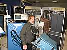
Bob ensnared
I know this looks staged - but Bob rose from a deep crouch and this happened.


Late in the day, while "no one was looking", one or more pixies delivered some storage,
possibly in response to Bill Flora's concerns, above.
"We think we are homing in on another print problem.
The print buffer is supposed to block the I to EX transition of a second print instruction if that instruction arrives
before the first print instruction is finished. This interlock does not seem to be working. This is a new area
of the machine for me to learn. I don't know how big of a hairball it is yet. Nothing seems to be written about
how this mechanism is supposed to work."
Ron Williams and Bob Feretich have been struggling for several months restoring the 1401 printer controller.
Our model is a buffered version which permits considerable overlap of computing and printing. This involves
an additional core memory.
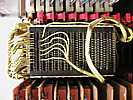
Side View
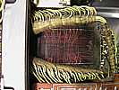
Top View
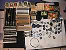
Here is a stash of spares organized by
Bob Erickson working on aligning the 026 key punch with "help" by Ed Thelen and visitors

Ron Williams playing "Kilroy Was Here" with a 1401 gate rather than the usual fence.
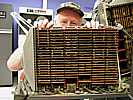
Ron Williams turned on the computer, and smelled the unforgettable, penetrating,
odor of scorching composition resistor. (I guess following his nose,) he found the
problem card, and determined the ultimate problem to be a short in a wire bundle to
the 1406 Extended Memory.
Somebody had rotated the 1406 90 degrees, and not been careful to observe the
cables leading into the unit - wires were abraded (I can't spell scraped or scrapped)
and the resulting short was heating/burning the resistor.
Past events and reports above this line. Future events below this line.
