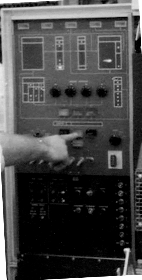
Evolution of the 1401 Control Panel
- Background, A-Test, B-Test, C-Test
- A-Test
- B-Test
Background, A-Test, B-Test, C-Test
From IBM 1401 Memories from Endicott by John Pokoski
(paragraphs two and three in "The Race for an Inexpensive Accounting Machine" )"When I joined the group, much of the design of the first prototype was completed, and it was being assembled in the lab. After testing and debugging in our own lab, it moved on to a separate group called "product test" that had to independently check it for meeting specifications and for reliability. This was called "A-test". Temperature, humidity, and power variations were used in this testing. If it passed ok, and the market was still there, the machine was announced, and the salesmen went to work.
"While this was going on, a second prototype was being built, incorporating everything learned, all engineering changes, some new technology, and optional features. This would be the prototype used for manufacture, and would also go through product test ("B-test"). The first machine manufactured at the factory went through "C-test". Once the machine was announced, training courses had to be set up for salesmen, programmers, customer engineers, factory engineers and technicians, and even customers. This was truly a big operation, and a lot was at stake."
Robert noticed differences between the IBM 1401 "A Test" Control Panel in the above photo, (left)
So he sent the following to Jud -
If Start/Stop, your finger is then likely pointing at the Start button?
What about Power On and Off? Previously a rotary switch? What about Tape Load?
And what prompted Tape Backspace to make its way to the front pane?
Do you recall anything else about the control panel design and changes? :)
(Fran proudly recounted to me how he had personally designed the layout - a reflection of the data paths.)
A-Test Control Panel

Jud McCarthy mailed a copy of a photo he used on the cover of his
book
to Robert Garner.
This picture was labeled "JudMcCarthy_1401SysATestUnit_1959.jpg", implying a prototype pre-production unit.
and the production systems on display and demonstrated at CHM. (right)


Besides cosmetic differences, do you recall how the control panel's buttons and switches evolved from System A to the product version? And what motivated them ? I've attached photos of each below (the latter of the CT 1401 panel, w/o Overlap). My observations/questions. :)
(A reflection of Fran's optimism(?), as I understand you guys firmly established the need for a Reset button
and Check Reset and disabling of I/O Check stop.)