return to main page

The Struggle Continues

Activity Report Nov 03, 2004
Updated Nov 04 with comments by Grady Keeton of Elgar technical support

Big day, lots of folks:

Allen Palmer, Don Cull, Ed Thelen, Frank King, Glen Lea, Milt Thomas, Robert Garner, Ron Williams and ex-officio member ;-)) Paula Jabloner - CHM archivist

  1. Further investigation of 50 Hz power supply problems
    Banging our heads on problems - see extensive report below.
    Comments by Grady Keeton of Elgar technical support.

  2. Start of search for more 1401 schematics and documentation in CHM archives with archivist Paula Jabloner
    - Milt Thomas spent full time sorting material and filling forms for data base entry - Paula had hoped for more people to press this ahead but problems with power ( #1 above) sucked off help

  3. Continue 729 tape restoration
    after giving up on Elgar as power supply for 1401, Allen and Ed tested the second 729 tape unit :-))
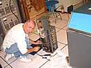
    Somehow, I thought electronics was a white collar job. IBM folks in blue suits saying "Yes Sir", and I don't know what else ;-))
    Is that Ed Thelen back seat driving, or contributing or ...
    Actually, the sad fact is that we could not remember how we tested an identical power supply a month ago, and are re-discovering how. :-((
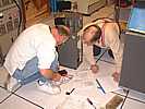
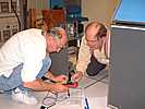
  4. Continue 1402 reader/punch - replacement and work

    good
    Don Cull exchanged the Punch Feed mechanism with the Visable Storage 1402
    bad

  5. Continue 1403 printer -chain and restoration
    Frank King continued work on chain. When he turned on the 1403 printer power when the 1401 was powered up, the Elgar power supply quit.
End of activity report summary.
Details below

Ed Thelen - Recorder

ELGAR Details

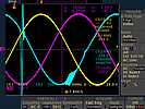
Robert Garner brought in a modern Tekronix four channel storage scope. I finally asked how much it cost - Robert said something like "You don't want to know".

from Robert Garner


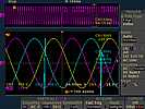
Figure 1.
SteadyState1401
The color codes are PhA=Yellow, PhB=Blue, PhC=Magenta, from top, middle, bottom Elgar 1750, respectively. However, note that the phase order on the scope is;
      PhA(yellow), PhC(magenta), then PhB(blue).

Why are PhC and PhB reversed in time?


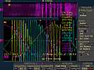
Figure 2.
Startup1401and1406

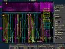
Figure 3.
Startup1401

Figure 4.
SteadyState1401CloseUp

The very-high voltage glitches on the Elgar output = 1401's input as its ferro-resonant supplies are coming up (lasts for ~5 seconds) look horrible.  After the startup period, they seem to go away. However, the last pic shows a steady-state glitch in Phase B, which is mainly powering the ~36 fans in the 1401. (The only ferro on PhB is not loaded.)

Here are the surprisingly-high input current and power reading, which represent an amazing INefficiency, or some other problem. Also note that "PhC" (the bottom Elgar) rises before "PhB" (in the middle Elgar) in time on the scope.

  PhA          PhB       PhC
ACInput- No load         2.1A         2.7A         2.9A
ACInput-1402 on         2.9A         3.6A         3.7A
ACInput-1401 on        20A        25A        24A
ACOutput-1401 on         5.5A         6.2A         0.7A
Table 1.
Converting to Volts*Amps (watts): with ACOutput = 220VAC to netural, 50 Hz; and ACInput = 208VAC to netural, 60Hz.
  PhA          PhB       PhC Total
ACInput- No load         440VA         560VA         600VA     1.6kVA
ACInput- 1402 on         600VA         750VA         770VA      2.1kVA
ACInput- 1401 on        4.2kVA        5.2kVA        5.0kVA     14kVA
ACOutput-1401 on        1.2kVA        1.4kVA         150VA     2.7kVA
Table 2.
The total AC input power of 14kW for only 2.7kW output, is an efficiency of barely 20%!  That can't be right. It's also very surprising to me that the 3 Elgars would dissipate 1.6kW with no output load at all! Perhaps our output jumpers for 2x voltage are incorrect?

And, of course, after just ~5 mins the wall circuit breaker trips!   At 30A, 208VAC, 3-phase, this correpsonds to 18.7 kVA of power!!  (Perhaps goes up as Elgars warm up.)

- Robert


from Robert Garner


Thinking about the glitchy power traces this evening, I think they're probably caused by a 1402 mechanical contactor oscillating open and closed, and are not coming from the Elgar.

One hint can be seen in the 1401+1406 pic: all three phases oscillate open/closed at the same time. Another is that when the relay re-contacts, the Elgar's AC voltage is right where it should be in the sine wave.

Also, the glitch widths (~1 ms) and bouncy nature are commensurate with a relay opening and closing. The quick voltage edge rates are consistent with mechanical contacts breaking and closing in inductive wiring.

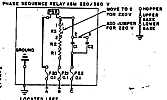
The 1402 has a small, simple circuit (below-I don't totally understand yet) that checks if the phases are in phase order. If not, it opens the 30VAC main contactor hold down circuit. I'm now thinking that this hold down circuit is oscillating. The PSR is trying to open up (after all, the phases are out of order), but can only hold the relay open for ~1 ms. We did notice it was misbehaving (allowing the main contactor to close, even when one phase was not on, etc.). We can just disable it, and bypass PSR. (We don't care if the phases are out of order at this point as motors are all disconnected.). There are also 4-5 other relays in the main contactor hold down path, both in the 1402 and the 1401.

Regarding the huge Elgar input currents, we need to review the AC input wiring configuration and voltages....

- Robert

p.s.

Figure 5.
1402PhaseOrderCheck
Here's the phase order check circuit. Bad caps or resistors would screw it up.


I called Grady Keeton of Elgar technical support 1-800-773-5427 Nov 4th, and gave him the URL of the Elgar wave form pictures and discussion http://www.ed-thelen.org/1401Project/ActivityReport-Nov03.html#below

He examined them and called back - we talked for 45 minutes :-))

I took hopefully good notes. The following is unaudited/verified by Grady. I will ask for his verification and/or corrections during the coming business day.

  1. He agreed that a chattering contactor and inductive kick might be causing the initial wild waveforms of Figures 2 & 3..

    I asked about how the Elgar handles current overloads - did they cut off the current on overcurrent? (If so, feeding an inductive load could cause those wild voltage spikes.

    Grady said the current on overload is tapered down, but not cut off, and the limiting action likely is not causing the size of the spikes being seen

  2. Grady suggests jumpering around the phase detection circuit to see if that might be chattering under high (starting) load conditions. (I think that Ron Williams has already done that, but not sure.)

  3. We really didn't get into possible causes of the spiking in Figures 1 & 4. There was some discussion of possibly being caused by action of the ferroresonant voltage regulators - but no one was really satisfied. Grady will look for and examine ferroresonant voltage regulator documents.

  4. About the unbalance in the input currents between the Elgar phase chassis in Table 1. - Grady suggests that there is a normal manufacturing tolerance - plus one or more of the fans might have been replaced with different characteristics.

    Also, just a reminder, all three input phases contribute to each output phase. (The low output phase "C" current should not necessarily mean a low input phase "C" current.

  5. The load also has a high harmonic content

  6. Considering KVA only, at high loads it takes about 3 KVA input to the unit to get 1 KVA out.

  7. Assuming that the load of each 220 volt output phase is 1.7 KVA, that would require three times the KVA from the wall circuit breaker. This would be 3 * 1.7 KVA each phase or 5.1 KVA per phase from wall. We are using 208 phase to phase from the wall circuit breaker. This is 115 volts phase to neutral.
    5100/115 = 44 amps.
    Our wall circuit breakers are rated at 30 amps. !!!

  8. Table 2. Table of watts, the Elgar using the transformer->diode-> capacitor has an effective power factor of about 0.6 at full load.

    Measuring just voltage and current gives KVA, not necessarily watts, 1000 KVA with a 0.6 power factor is 600 watts.

  9. Figure 5. How the relative phase sense circuit works. Grady gave an explanation very similar to URL http://www.allaboutcircuits.com/vol_2/chpt_10/3.html Robert is correct, it can be simulated with SPICE :-))

  10. There is no commercial phase rotation standard. That is, you take delivery of three phases, and commercially there is no defined rotation.

    There is a rotational Mil Standard 704, used for aircraft bus power.

    Commercially - if you don't like the rotation, just swap two leads - and be happy (my words ;-))

  11. I expressed concern about idle hands or casual bumps causing changes to voltage and frequency dials.

    Grady mentioned that he might be able to send us an amplitude locking collar, that when tightened, prevents inadvertent changes in the voltage setting.

    Grady suggested a plastic shield over the frequency dial could be helpful in preventing inadvertent changes.

    I showed Grady photos of our particular system. He was quite interested in the top chassis - which is likely custom built. If we provide him nameplate numbers, he might be able to locate prints for us.

  12. Grady said that it is not practical for us to send this unit to Elgar for service, nor is it practical to get an expert here to look at it. The unit is about 30 years old, and spare parts are getting chancy.

    We can do local tests and adjustments to verify performance.

    Grady suggested getting a suitable stove heating element and testing each phase individually (there is no interaction expected assuming reasonable regulation of the input power. This would provide a very polite resistive load as a benchmark verification.

    He also said that current limiting adjustments are practical in the field - he told and can send instructions.

    The output regulation adjustment is also practical in the field.

    One of the heat sinks is also arranged with an overheat sensor that also protects the Elgar.

I asked to terminate the discussion as other items were intruding into my life. Grady is interested in our 1401 restoration effort and willing to talk further :-)) He lives in San Diego, and I have sent him a list of interesting things for him and his family in the San Francisco Bay Area.

--Ed Thelen