729 Test Set

|

|
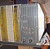
NOTE - Neither the instrument we have above

| nor the TapeAdaptor in the 1401 |
The following translated from German by Alex Bochannek
5 Test-Equipment
| Table of Contents: Page | |||||||||
| 5.1 Transportable Tape Drive Field Tester for 729 II and IV1 49 | |||||||||
| 49
| 50
| 50
| 51
| 51
| |
5.1 Transportable Tape Drive Field Tester for 729 II and IV
5.1.1 General
This "Tape Drive Test" (TDT) verifies the mechanical and electrical
functions of the 729 II and IV. All signals coming from the tape unit are
verified by the tester.
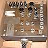
The tester is housed in a portable metal case.
Dimensions: 16" length, 9" width, 8" height. The plate with the controls is
located in a detachable lid, which has mounted the circuit diagram on its
inside. The circuits are contained in 10 transistor board. Part of the
tester is an 8 foot long signal cable with "Low Voltage"-plug and an 8 foot
long control cable with Jones-plug. The voltage necessary for operation of
the tester is supplied by the "Tape Unit". After removal of the 6 screws of
the switch plate, the inside of the tester is accessible.
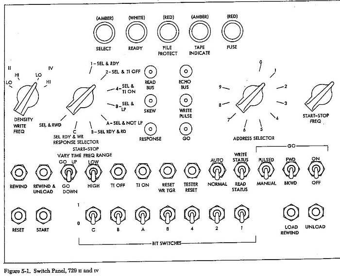
5.1.2. Indication Lamps (Illustration 5-1)
All indicator lamps of the tester operate in parallel to the laps of the
tape unit.
Select Lamp: Illuminates when the tape unit and the TDT have selected the
same address.
Ready Lamp: Illuminates when the tape unit is in the Ready State. This is
the case when the start button has been pressed, the tape unit has been
loaded, the door contact has been closed and the tape unit is neither in a
load nor rewind operation.
File Protect Lamp: Lit when writing is not supposed to happen. The "File
Protect"-ring is not on the reel, the system is in a load or
rewind-operation, it is in the unload status or is carrying out an unload
operation.
Tape Indicator Lamp: Illuminates when an "End of Reel Reflective Sport" is
sense while in write status, also when the key TI ON is pressed on the
tester. It is extinguished when the key TI OFF is pressed on the tester or
the key Unload (729 or tester) is pressed.
5.1.3 Switches (Illustration 5-1)
Address Select: This turn switch has 10 positions (0 - 9) that are
equivalent to the Selekt switches on the tape unit. If both switches
correspond the SELECT lamp is illuminated.
Bit Switch: These 7 switches determine if in the associated tracks bits are
written or not while the tape moves in write status past the head.
GO-Forward-Backward: This switch determines if the tape moves forward or
backward when the GO switch is set to ON.
Response Selector: This turn switch has 2 switch levels of which the one
selects the different "Read Buses" which are made available on the READ-BUS
pin, while the other is used to select the different Response lines and to
make them available on the RESPONSE pin. The selectable Response lines are:
"Select and Ready", "Select and TI OFF", "Select and TI ON", "Select and at
Load Point", "Select and Not at Load Point", "Select Ready and Read",
"Select Ready and Write", "Select and Rewind", and Density.
Read-Write Status: This switches takes the tape unit into Read or Write
status. In the Write position the pulses of the sweep circuit can be
measured on the WRITE PULSE pin. In position READ the outputs of the
preamplifier, based on the selected track, can be measured on the READ BUS
pin.
Write Frequency: This switch makes available two fixed write frequencies,
namely 67usec and 24usec in 729 II, and 24usec and 16usec in 729 IV,
respectively.
Rewind: Pressing this key will prompt the tape unit to carry out a rewind
operation if Select and Ready and the switch AUTO NORMAL is in the position
"Normal".
Rewind and Unload: Pressing this key will prompt the tape unit to carry out
a rewind operation followed by an unload operation. Should the tape be
already positioned at the "Load Point", only the unload operation will be
carried out.
TI ON: Pressing this key takes the "Tape Indicator" in the tape unit to ON
and illuminates the "Tape Indicator" lamps in the tester and in the tape
unit.
TI OFF: Pressing this key extinguishes both "Tape Indicator" lamps in the
tester and the tape unit if the AUTO NORMAL switch is in the position
normal.
Reset Write Triggers: The 7 Write Triggers are reset by pressing this key.
Pulsed Manual: In the position PULSED the GO-sweep circuit controls the
start and stop frequency of the tape. The desired frequency can be obtained
by twisting the knob.
Start/Stop Frequency: Selected and has a range of 0.25 to 13.5 msec. In
position MANUAL the sweep circuit is disconnected and the tape moves now,
assuming the GO-ON-OFF switch is ON, with constant speed. Both positions,
PULSED and MANUAL can be used as well for Read as for Write.
Tester Reset: Through this key the trigger in the tester, which through
sensing of TI or LP was tipped in (depending on Forward or Backward), will
be reset. The GO-Line will be "gated" through this trigger and motion of
the tape is only possible after a reset.
GO UP/GO DOWN: With this switch it can be selected if via the "Start/Stop
Frequency"-potentiometer the GO-UP or GO-DOWN time should be varied.
HI LO: With this switch 2 ranges for the GO-UP and GO-DOWN times can be
selected. LO range: 2 to 110 msec, HI range: 1 to 7 sec.
Reset: Through this key any currently running operation, Unload excepted,
can be stopped. (TI cannot be reset by pushing Reset).
Unload: This key initiates an Unload operation. It is only effective if the
tape unit is in MANUAL CONTROL (by pressing Reset). Also, by pressing
Unload, the "Tape Indicator" is reset.
5.1.4 Lead Pins
Echo Bus: The "Write Echo" of all seven tracks can be measured on this pin.
Read Bus: The preamplifier output of each track can be measured here.
GO: This is the the output of the GO-sweep circuit. The signal is used to
synchronize the scope when measuring the start-stop-time.
Response: The lines mention in section 5.1.3 under "Response Select" are
available here.
Skew: Read-Bus 1 is available here for convenient scope synchronization
when measuring skew.
Write Pulse: When the "Read Write" switch is in position write, write
pulses are available here.
5.1.5 Operation
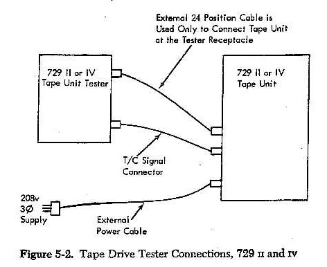
In order to control a tape unit from the tester, at first the two cables
connections between the tape unit and the tester must be made and the tape
unit must be powered on. The tape should have a "Load Point" and an "End of
Reel Reflective Spot". A "File Protect" ring should be inserted (never
insert a "File Protect" ring into the "Skew Mastertape"). Press the Start
button, bring the select switches on the tester and the tape unit in
corresponding positions, reset TI if on, select the Forward position of the
"Forward-Backward" switch.
Write: Set the switches listed under Write in illustration 5-3 to the
indicated positions. The ON-OFF switch is to be set last. If TI is not on,
the tape will move forward and write bits into the tracks whose
bit-switches are set. Observer the write pulses on the lead pin "Write Bus"
with the scope. The write operation is interrupted when ON-OFF switch is
set to OFF.
Read: Set teh "Read Write" switch to Read, ON-OFF switch (GO) to ON. On the
lead pin READ BUS the preamplifier output of the track selected with with
the select switch. GO switch to OFF interrupts the Read operation.
Auto-Cycle: The "Auto Cycle" facility can be use to test the following
operations: Sensing of EOR (end of reel) and LP (load point, "High Speed
Rewind", faultless function of vacuum-switches, flapper valves and
associated circuits. The facility operates as follows: Read or write a tape
forward until the EOR-Reflective Sport is sensed. Then automatic rewind to
the LP. Immediately after reaching the LP the tape starts again and so on.
If one puts the EOR-Spot only a few feet removed from the LP the "Auto
Cycle" will be very short, through which one can easily test the LP- and
EOR-photocells and the "Single Shots". If the EOR-spot is positioned such
that the tape unit can barely reach "High Speed Rewind" and the LP shortly
before that, one with ease test conduct a test of the vacuum system and its
switches.
With a full reel with an EOR-spot at the the end the whole "High Speed
Rewind" operation can be checked.
Tester and tape unit can run in these "Auto Cycles" for a while to test the
reliability of the "High Speed Rewind".
The "Pulsed Normal" switch can be moved to the Pulsed position and operate
together with the "Auto Cycle". The tape runs now in a the Start-Stop
frequency.
Start/Stop: Before the tape unit is operated in the Start/Stop state, the
write frequency needs to be selected and bits written on all tracks. In
order for the tape to be transported forward, the following switches are to
be set:
In order for the tape to be transported backwards, only the FWD/BKWD needs
to be set to BKWD instead of FWD. All other switch positions remain the
same.
During the Start/Stop operation the GO and "Read Bus" lines can be tested
on the test leads.
Tape Indicator: To test the function of the "Tape Indicator", a EOT-Spot
(End-of-Tape marker) needs to be affixed several feet (foot = approx. 33cm)
from the LP-spot (Load-Point marker). The switches on the tester are to be
set as follows:
Skew: The function of the the tester while testing skew (offset of the
magnetic bits within a character) can be divided into three operations:
Mechanical skew, write-skew, and read-skew. The switch positions for these
test operations are listed in illustration 5-3


return to main page